Beer Forum

This is a forum for enlisted and new recruits of the BN Army. Home brewers bringing it strong! Learn how to brew beer, trade secrets, or talk trash about your friends.
http://www.thebrewingnetwork.com/forum/

Wiring up loves & ascos

http://www.thebrewingnetwork.com/forum/viewtopic.php?f=3&t=11184

Page 1 of 3

Wiring up loves & ascos

Posted: Sun Oct 12, 2008 2:38 pm
by triple-oh-six
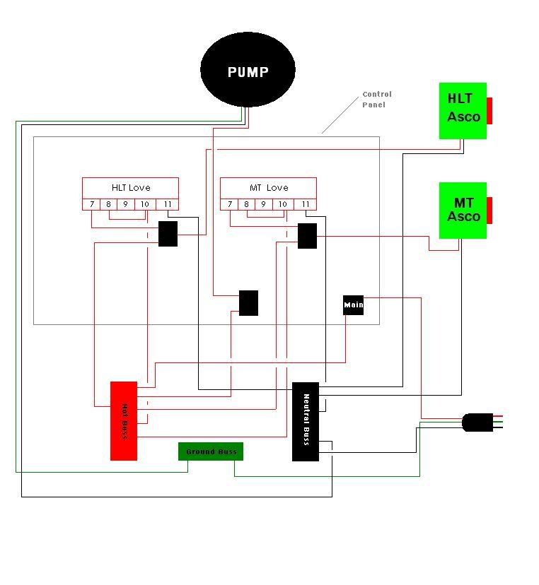
So, I'm just about 1/2 done wiring up my control panel.
I seem to have confused myself and need some help.

What I'd like to do is have a 3 position toggle for:

Position 1 - Love controls asco
Position 2 - Off Asco closed
Position 3 - Direct power Asco open

I bought a DPDT toggle which is what I thought I would need but now I'm unsure.

The Loves are powered up by the main power switch so I have no need for a toggle on them.

The DPDT switch that I have has 6 posts:

Load "A2"
Load "B2"
Line "A"
Load "A1"
Load "B1"
Line "B"

Would this switch even work for what I want?

I'm know what I'm w/ DC, and I've done some simple home wiring before but I can't quite read wiring diagrams unless they are really simple.

I've got someone who's supposed to help me this week but I'm just impatient and want to do it myself.

Thanks for any help.

Re: Wiring up loves & ascos

Posted: Sun Oct 12, 2008 2:45 pm
by grod
whats wrong with trial and error? After all its only electricity.

on a serious note, wait for your mate triple.

love

g

Re: Wiring up loves & ascos

Posted: Sun Oct 12, 2008 3:47 pm
by codewritinfool
Disclaimer: I am not an electrician. I do not own a Love controller. I do not own an ASCO valve. If you are still interested, read on.

Image

This should do what you are asking. Since you stated you didn't want to shut off your Love controllers, I did it this way. You only really need half of your switch, but that's ok.

The switch is shown in position one - Love control. AC is passed from LINE B to LOAD B1 and on to the Love relay common. When the Love wants to it can close its relay and power the ASCO.

Position two is not shown but you can think of it in your head as being in between LOAD B1 and LOAD B2. No AC flows to either the Love relay or the ASCO.

Position three would be with the switch down. AC is passed from LINE B to LOAD B2 and directly to the ASCO. In this case the Love relay has no bearing on the operation. ASCO is powered on all of the time.

Note that when wires cross on the schematic, a DOT indicates a connection.
Do not break the neutral at any point in the circuit.
Make sure everything is properly grounded.
Preferably use a GFCI as a source of your power.
Test outside.

Re: Wiring up loves & ascos

Posted: Sun Oct 12, 2008 5:13 pm
by triple-oh-six
Thanks Code, that's awesome.

I plan on getting back to it tommorrow.
I'm a bit drunk and I don't wanna screw something up.
I cooked prof. for years and burnt myself a lot so heat I can handle,.... shocking, not so much.

I think that's what I needed though.

Prost

Re: Wiring up loves & ascos

Posted: Mon Oct 13, 2008 8:59 pm
by triple-oh-six
Well, I tried the configuration above from Code and it didn't work b/c I want to have power to the loves even while bypassing them.

I'm no good with diagrams so I just drew it out.

My main question is that will the switches work with the loads/line flipped.
I guessing that the current will flow either way, but I've been wrong before.

Also as far as I could tell from a few other peoples diagrams that is how the Loves should be wired.

I feel so retarded when it comes to this shit. :asshat:

Thanks

Image

Re: Wiring up loves & ascos

Posted: Mon Oct 13, 2008 9:45 pm
by codewritinfool
The way I presented it the Loves power is not even addressed - you already stated that they are controlled by the main power and you didn't want to have them affected by the new switch. The diagram presented is just a portion of the overall hookup, focusing exclusively on the new switch and the functionality you desire.

Sorry, but I think you are confusing Love power with relay common. Like I said, I do not own a Love controller, but I am certain that its relay contacts are all brought out independently - without looking at a diagram, I suspect that your jumper between 8 and 10 is the Love line hot to relay common. This jumper cannot be in place if you use my diagram. Remember, I don't even address the Love power - you already have that, so if the Loves used to be powered on via the main only and now they are affected by the new switch, then they are wired incorrectly.

I am confident that my diagram is a correct solution for what you asked for. It is only one method to achieve what you want; there are certainly others. If you'd like me to redraw it with the Love terminal numbers on it, I can.

Re: Wiring up loves & ascos

Posted: Tue Oct 14, 2008 2:28 am
by Sent From My iPhone
Image

Re: Wiring up loves & ascos

Posted: Tue Oct 14, 2008 5:32 am
by WitsEnd
Both diagrams should work.

Code has located the switch before the love controller so that the power either goes directly to the asco valve OR to the love controller. As he noted, he only illustrated the lines powering the asco valve and not the main love power. He's right about your jumper between #10 and #8.

Here's how to think about your love controller in the form of simple switches:

The love controller needs a power supply. That's your #10 and #11 as shown on your diagram.
When powered, the love controller acts as a switch. #7 and #8 are your switch posts.

All times are UTC - 8 hours
Page 1 of 3